

A solar cell is a diode. Push current through it in the forward direction and it emits a faint near-infrared glow, the reverse of how it turns light into current. Electroluminescence (EL) imaging photographs that glow across the whole module in the dark. Where the cell works, it shines; where it is cracked, disconnected or shunted, it stays dark.
What EL reveals
- Cracks and microcracks: dark lines, sometimes isolating part of a cell.
- Broken or interrupted fingers: dark stripes along the grid lines.
- Inactive areas: cell regions cut off by cracks, completely dark.
- Shunts and contact faults: uneven brightness or dark spots.
- Process signatures: patterns from soldering, lamination or handling.
Why a power measurement is not enough
A freshly cracked cell can still conduct, so the module may rate close to nameplate on the day it is flashed. Under thermal cycling, wind and snow load the crack opens, isolated areas grow and power is lost in the field. EL shows the damage before it becomes a warranty claim.
How the measurement is done
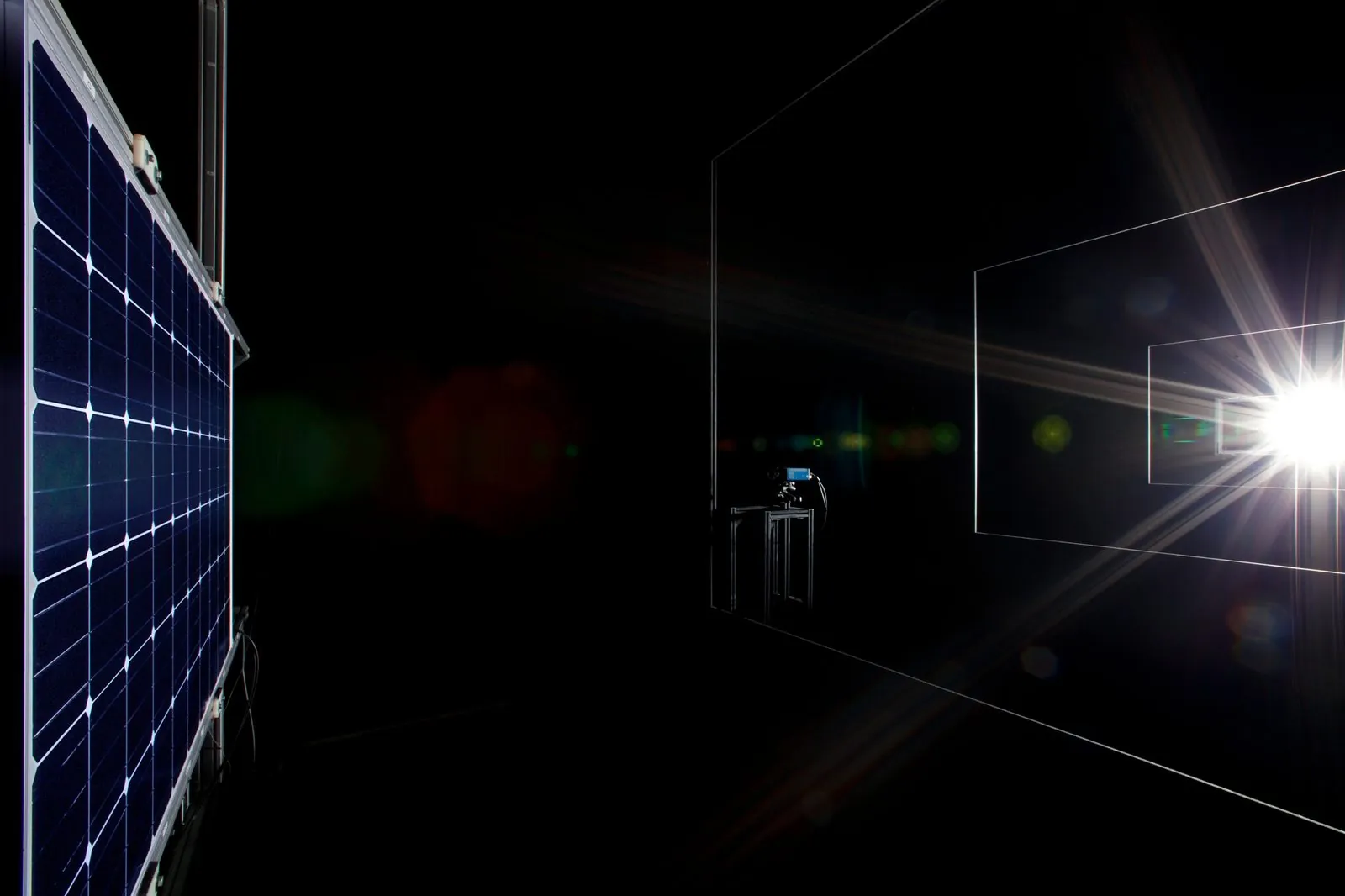
The module is connected to a DC supply in forward bias, typically at a current close to its short-circuit current, inside a dark enclosure. A camera sensitive to the near infrared images the whole module. IEC TS 60904-13 describes the method and how images are acquired and evaluated. Imaging at a second, lower current helps to separate resistive faults from shunts.
EL in a measurement line
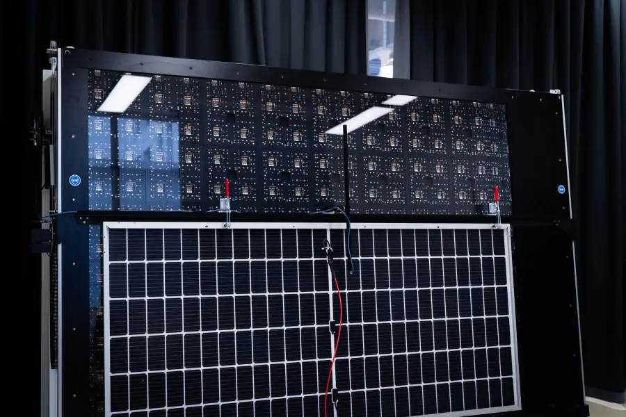
The efficient place for EL is next to the power measurement, on the same contact. Pasan EL Inspection switches the module between I-V and EL without moving it, and interlocks the switch in firmware: the bias supply is turned off and confirmed off, the module is discharged and checked at zero volts, and only then does the relay change over. Every module leaves with a rating and an EL image under the same serial.
Frequently asked questions
- What is electroluminescence testing of solar panels?
- EL testing drives a PV module in forward bias in the dark and images the near-infrared light its cells emit. Working cell areas shine; cracks, broken fingers, inactive areas and shunts appear dark.
- Which standard covers EL imaging of PV modules?
- IEC TS 60904-13 describes electroluminescence imaging of photovoltaic modules.
- Can a cracked module still pass a power test?
- Yes. A fresh crack can still conduct, so the module may rate close to nameplate, then lose power in the field as the crack opens. EL imaging shows the crack directly.
- Can EL and I-V be measured on the same station?
- Yes. Pasan EL Inspection shares the flasher’s contacting and switches between I-V and EL through an interlocked relay, so each module gets a power rating and an EL image without being moved.