



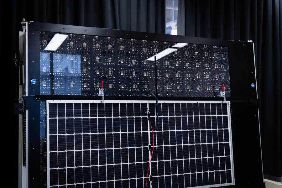
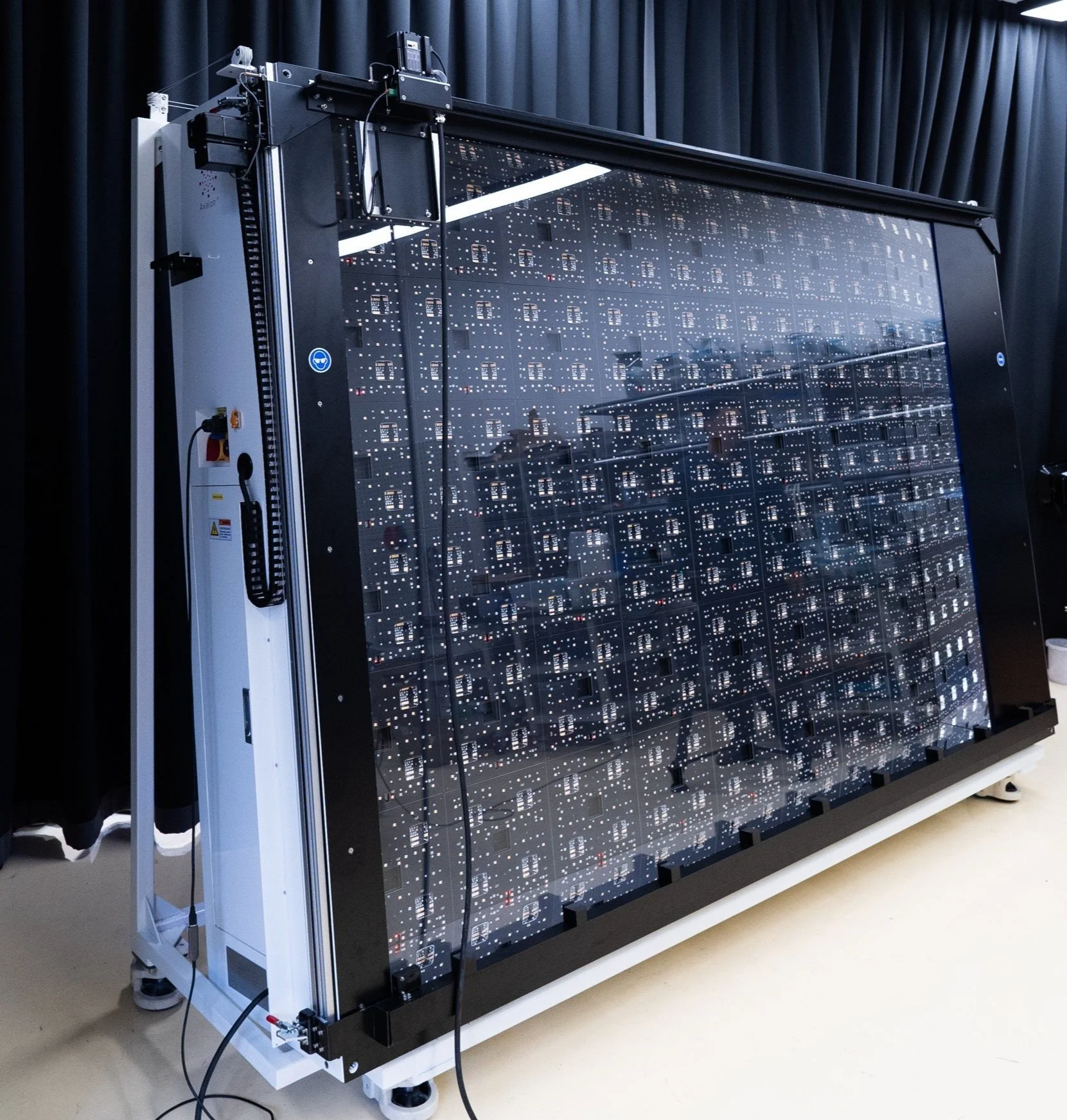
 Electroluminescence Imaging
Electrical safety test
HiPot Testing
Up to 6 kV, on the same station as the I‑V flash.
A PV module spends 25 years at up to 1500 V, behind a metal frame that people touch. The HiPot test proves, on every module before it leaves the factory, that the insulation holds well above that voltage and that the frame is properly bonded. On a Nexun it runs right after the flash and the electroluminescence picture, without moving the module.
Why every module
A flash shows the power. HiPot shows the module is safe.
An I‑V curve can look perfect on a module with a pinched backsheet, a cracked glass edge or a junction box that sits too close to the frame. Those faults do not cost a watt on day one. They show up later, as a ground fault in the field, a tripped inverter or a frame that should never carry voltage.
Insulation that holds
Live parts (cells, ribbons, junction box) are lifted far above the system voltage against the frame. Weak insulation shows up as leakage current, or as a breakdown.
A frame that is bonded
The frame must connect cleanly to earth. A loose or missing bond shows up as a continuity resistance that is too high.
Proof for every serial number
Type approval tests a handful of samples. A routine HiPot test on the line gives every shipped module its own recorded pass, next to its I‑V curve and EL picture.
What it measures
Three tests, one run
Each panel type gets its own test plan. The steps run in order, and a step that does not pass ends the test, so a module never goes on to the next one with a known fault.
- DCW · up to 6 kV DC
Dielectric withstand
The voltage ramps up to the set level, up to 6 kV DC, and holds for the dwell time. The leakage current is checked against a high limit (insulation too weak) and a low limit (no current at all means the test contact never reached the module).
- IR · MΩ
Insulation resistance
At a set test voltage, the insulation resistance between the shorted module leads and the frame is measured in megohms and compared with the minimum of the test plan.
- Ground bond · Ω
Frame continuity
Measured during the withstand, in the same run: the resistance of the frame bonding path, with the test leads' own resistance taken off, between a low and a high limit.
On the station
No second station, no second handling
The module is placed once. The leads that carried the I‑V flash are switched over to the HiPot tester, the test runs, and they are switched back.
- The I‑V flash measures the module, then the electroluminescence picture is taken if EL is fitted.
- As soon as nothing powers the module any more, a switchbox moves its leads from the I‑V load to the HiPot tester, after a short guard so no relay ever opens or closes under current.
- The test plan of that panel type runs: withstand, continuity, insulation resistance.
- The output switches off and the module is discharged before the leads go back to the load.
- The result, pass or fail with every measured value, is saved with the module's I‑V curve and EL picture, under its serial number.
Safety first
High voltage, handled like high voltage
The sequence around the test is fixed. It always runs to the end, whether the test passes, fails or is stopped.
Stop at any time
Stopping a test switches the high voltage off at once, not at the next reading.
No switching under current
Leads are only switched with a guard delay before and after, so no relay ever breaks a current or draws an arc.
Discharge before release
Output off, then a discharge wait, before the module goes back to the load or to the operator.
Interlocked with the flash and EL
No flash while a HiPot test runs, and no HiPot test while the EL supply still powers the module.
Specifications
HiPot option at a glance
- Dielectric withstand (DCW)
- 1 to 6 kV DC
- Ramp and dwell
- Set per test plan, in seconds
- Leakage current
- High and low limits, in mA
- Insulation resistance (IR)
- Test voltage and minimum resistance per test plan, in MΩ
- Frame continuity
- Low and high limits in Ω, lead offset, measured during the withstand
- Test plans
- One per panel type, picked from the module recipe
- Switching
- Automatic switchbox between the I‑V load and the tester
- Result
- Pass or fail per step, measured voltage, leakage, insulation resistance and continuity
- Software
- Pasan Studio, on the same screen as the I‑V and EL results
- Available on
- Nexun EVO, Nexun PRO, Nexun PRO Max
Limits and voltages are set by you, from your product's certification and your quality plan.
Standards
The tests behind the standards, on every module
The safety standards describe these tests for type approval. The HiPot option runs the same kind of test as a routine check in production, with the limits you set.
- IEC 61215-2 MQT 03
Insulation test
A withstand at 1000 V plus twice the maximum system voltage (4 kV for a 1500 V module), then an insulation resistance of at least 40 MΩ·m² for modules over 0.1 m². Up to 6 kV leaves headroom above that.
- IEC 61730-2 MST 16
Insulation test
The dielectric withstand of the module safety qualification, between live parts and accessible parts such as the frame.
- IEC 61730-2 MST 13
Continuity test of equipotential bonding
Checks that accessible conductive parts, the frame first, are bonded with a low resistance path.
Works with
Add HiPot to these Nexun systems
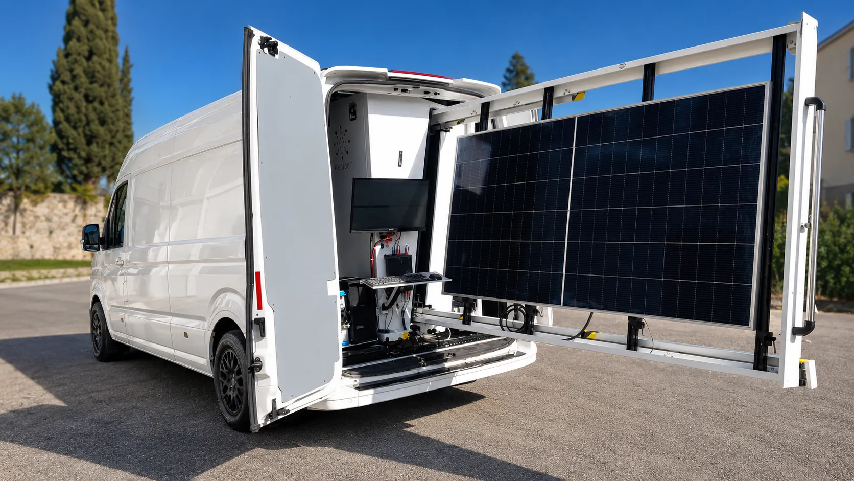
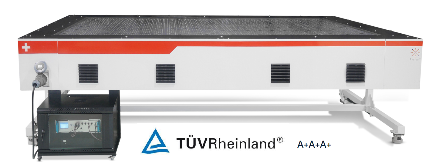
The HiPot option shares the station, the leads and the software with the I‑V flash.

Questions we are often asked
What is a HiPot test on a solar panel?
HiPot (high potential) puts a high DC voltage between the module's shorted electrical circuit and its frame, and measures how much current leaks through the insulation. A module that passes is insulated well above the voltage it will see in the field.
What is the difference between withstand and insulation resistance?
The withstand test applies a high voltage, up to 6 kV here, and watches the leakage current for a breakdown. The insulation resistance test applies a lower voltage and gives a value in megohms that you compare with a minimum. Both are in the same test plan.
Why run it in production when the module type is already certified?
Certification tests a few samples of a design. Production faults, such as a damaged backsheet, a lamination defect or a missing frame bond, happen to single modules. A routine test catches them before they ship.
Which machines offer the HiPot option?
The Nexun EVO, Nexun PRO and Nexun PRO Max. With electroluminescence imaging as well, the station tests I‑V, EL and HiPot in one placement of the module.
Rather we contact you?
Leave your email and we will get back to you. No form to fill in.
Every module, insulated and bonded. On record.
Tell us your module format, system voltage and line rate, and we will configure the station around them.